When you’re developing your projects at your workbench or your <politically_friendly_chosen_gender>-cave, supplying power is easy! You’re almost certainly hooked up to a mains supply in one way or another. Even if you’re using your laptop with a USB cable connected to your project, you’re still effectively supplying power from an external source.
Sometimes, it’s easy to overlook the geographical or utility restrictions of the area in which your project will be deployed.
Heck, sometimes – even when you know you need your own power source for your devices – it’s difficult to understand what that power supply should be, how much power you need to supply, how long the device needs to run on that supply etc.
Yes, you can connect a series of alkaline or nickel batteries, but will that give you what you need?
Also, how do you monitor that power supply? How does your program know when the batteries are running low?
In this article, we’re going to take a look at using Lithium Batteries with an Arduino and an ESP32 (respectively). We’re going to discover ways of connecting Lithium Batteries to our device, means of charging these batteries, how to obtain the correct device supply voltage from batteries, and – crucially – how to monitor the state of these batteries (both when charging and discharging).
Due to the vast quantity of information we need to cover, we’re going to break this article into two parts.
Part one (the part you’re reading now) will focus entirely on the Hardware side (components and wiring).
Part two (the final part) will focus entirely on the Software side (handling Lithium Batteries in your MCU programs).
Plug yourself in and charge up… we have a range to cover!
Discharge Curves:
Why you Can’t
Just Measure Voltage!
You may be familiar with basic concepts for using AREF (Reference Voltages) to determine the approximate remaining capacity in a battery.
This is the most common approach for Battery Monitoring when it comes to Alkaline or Lead-Acid Batteries, and it is extremely simple to implement in code. If you know the maximum voltage, and the present voltage, you can easily calculate the percentage remaining.
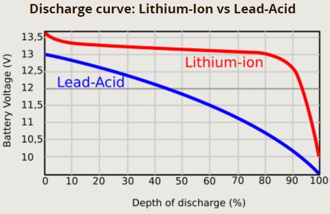
This works with Alkaline and Lead-Acid batteries because their discharge curves are fairly Linear. That is, the battery voltage drops in near-equal proportion to the overall remaining capacity.
However, Lithium is different! Lithium cells (be they Lithium Ion or Lithium Polymer) retain a very high voltage for the majority of their overall discharge cycle. Indeed, you will not see much variation in voltage with a Lithium Cell between 90% of its overall capacity, and 20%.
This means that we cannot rely on Reference Voltage to get any meaningful indication of the State of Charge for a Lithium Battery.
Indeed, this is precisely the reason for this (two-part) Article! To provide a means of reliability monitoring Lithium Batteries powering your device(s).
Before we dive into the solution, let’s talk about different Lithium Batteries, their pros, cons, and comparable properties.
Lithium-Ion (Li-Ion)
vs
Lithium Polymer (Li-Po)
| Attribute | Li-Ion | Li-Po |
|---|---|---|
| Low Usable Voltage | 3v | 3v |
| High Usable Voltage | 4.2v | 4.2v |
| Energy Density | Highest | Lower |
| Physical Flexibility | Very Low | Moderate |
| Mass/Weight | Heavier | Lighter |
| Volatility | High | Low |
| Charging Time | Slower | Faster |
| Cost | Inexpensive | Slightly more Expensive |
| Capacity | Lower | Approx 2x Higher |
| Operating Temperature Range | -20 to 60º C | -20 to 60º C |
| Impedance (Ω) | < 100 mΩ | < 50 mΩ |
| Charging Temperature Range | 0 to 40º C | 0 to 40º C |
| Optimum Storage Range | -20 to 35º C | -20 to 35º C |
| Consumer Serviceable/Replaceable | Yes (Replaceable) | No (typically sealed in device) |
| Common Usage Applications | Laptops, Electric Cars, UPS Devices, High-consumption Consumer Electronics (where replaceable batteries are required), Computer Peripherals | Tablets, Mobile Phones, Radio-Controlled Vehicles (Drones), Low-consumption Consumer Electronic devices such as Headphones/Earbuds |
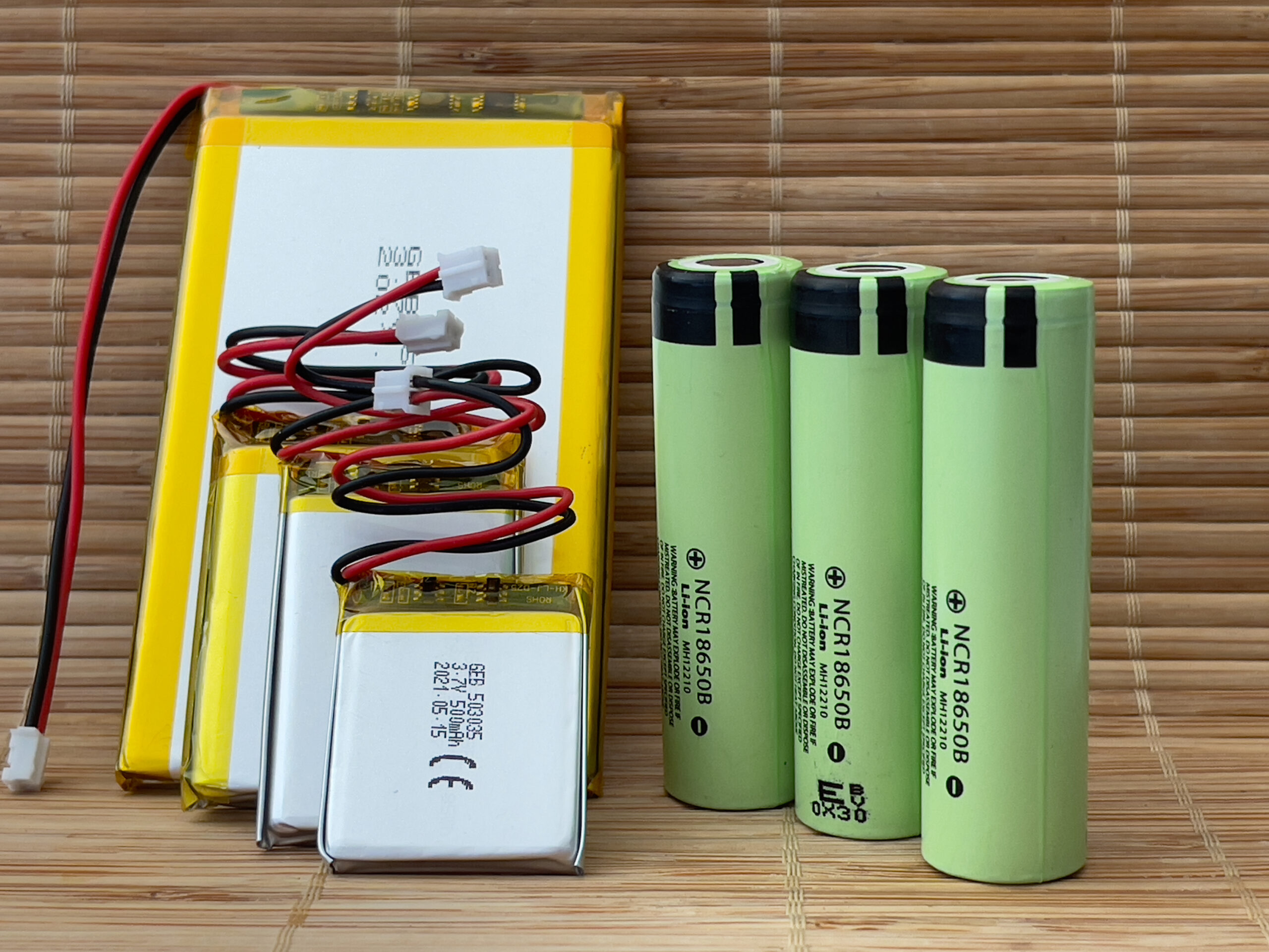
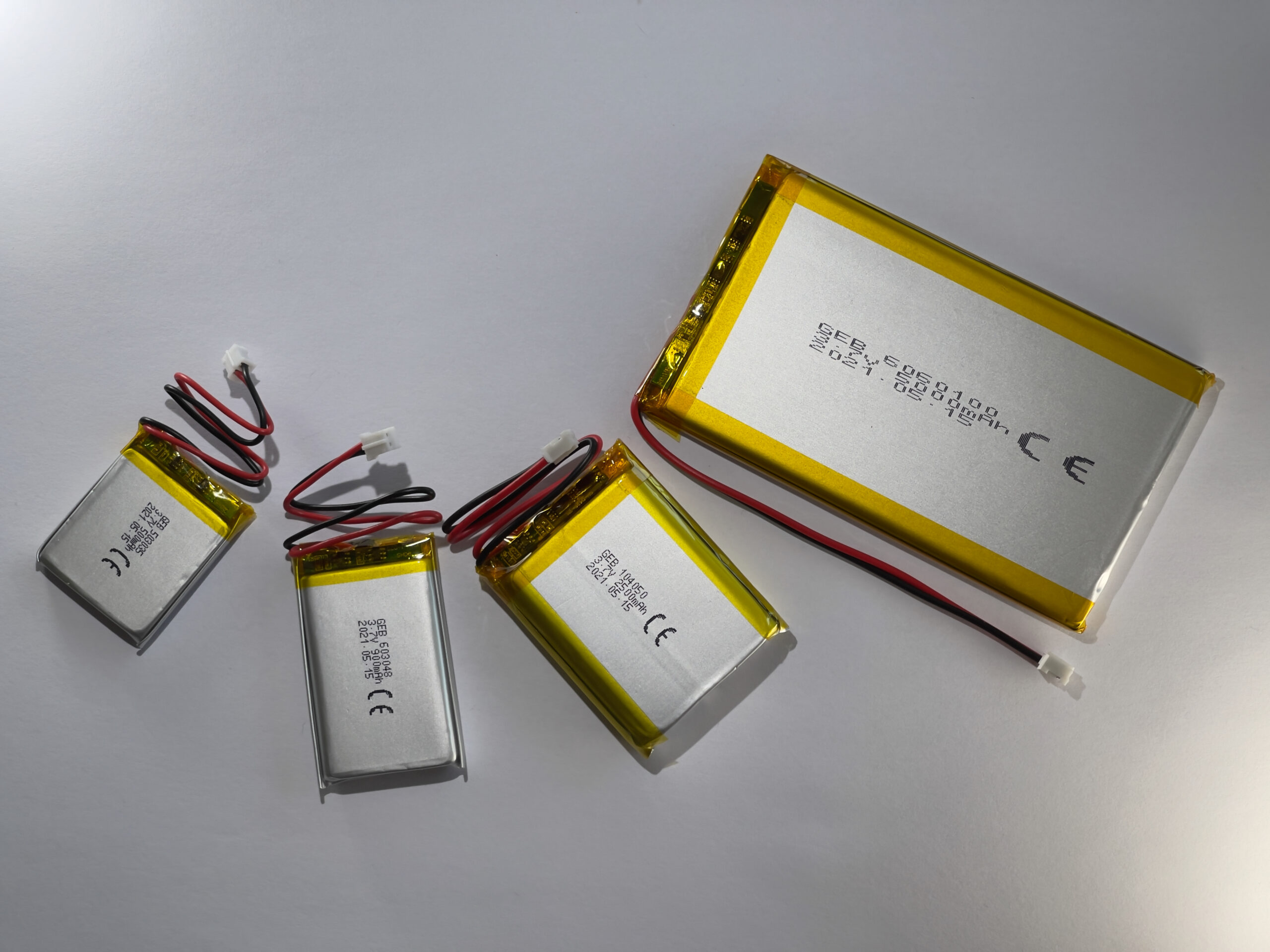
When choosing a battery for your device, you first need to decide what size and shape you’re looking for. Both Lithium Ion (Li-Ion) and Lithium Polymer (Li-Po) are comparable when it comes to power output potential, where Lithium Polymer does just have an edge in terms of overall runtime per-charge-per-volume.
However, Lithium Ion batteries weigh considerably more than Lithium Polymer, are inflexible (typically inside a metal casing for rigidity), and come in fixed form-factors, which could limit their usefulness in your projects.
Meanwhile, Lithium Polymer (Li-Po) are more flexible than their Li-Ion counterparts. Li-Po batteries are available in a greater range of form-factors, capacities, weights, dimensions etc.
While Li-Po batteries tend to have a lower maximum discharge/recharge cycle count than Li-Ion, they can be recharged more rapidly, and they can have as much as twice the runtime as their Li-Ion counterparts in terms of capacity by volume.
Li-Po batteries also retain a charge when in storage for considerably longer than Li-Ion, which can be a considerable advantage in devices capable of entering a Deep-Sleep State.
Indeed, lower volatility (less likely to catch fire) higher capacity per volume, lower mass (thus weight), and rapid charging are the primary reasons why RC craft (e.g. RC planes, helicopters, quad-copters etc) and robots tend to opt for Li-Po over Li-Ion.
Likewise, your Smartphone has a Li-Po battery simply because the weight and dimensions (form-factor) are considerably better for hand-held portable devices.
However, if your device consumes a lot of power, and requires that the operator be able to exchange batteries rapidly, you may prefer to use the Li-Ion in a standardised form-factor. This is because it is far easier and quicker for the end-user to replace a solid battery cell than it is to unplug and replace a semi-flexible Li-Po unit (which are almost always considered non-serviceable parts, and usually not accessible without complete device disassembly)
There are Battery Compartments available for all standardised Lithium Ion batteries, while Lithium Polymer cells come with wires for internal connection to your Device.
So, the choice of battery type is, ultimately, dependent entirely on your requirements.
A Guide For
All Batteries Lithium
Whether you determine that Lithium Polymer or Lithium Ion is the best choice for your project, this guide has you covered.
We will cover the considerations you need to make for your project, a few ways of calculating the best Capacity of battery for your project, how to get the voltage you need from your battery, charging the battery, and – quite probably the most important thing – keeping track of battery capacity and state.
We will go a step further, and produce a piece of code to keep track of your battery state, which you can use in your projects (a Library, released publicly for both the Arduino IDE and PlatformIO).
Boards
with
Built-In
Battery Circuits
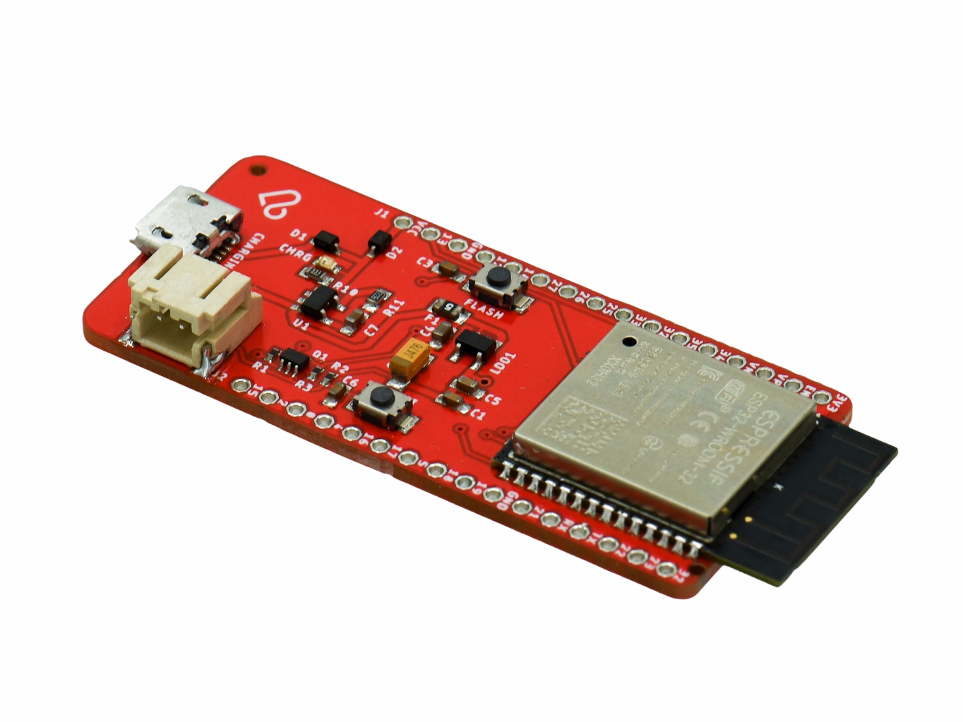
Some boards, such as the LPKit ESP32 Development Board pictured above, come with integrated Battery Circuits.
These boards make it easy to power your device using a Lithium battery, and can reduce the complexity of your own circuitry as you know already that your Development Board is receiving the correct voltage and current from a Lithium Battery source.
What you need to be aware of is that, even though such boards provide the means to supply power directly from a battery, they do not provide a means of interrogating the State of Charge for a Lithium battery!
Also, as you likely know, not all boards come with integrated Battery Circuits. Fortunately, it is fairly simple to add the additional circuitry we require to supply an ESP or Arduino (indeed, practically any) Development Board from a Lithium Battery.
TP4056
Lithium Ion
Charging Board
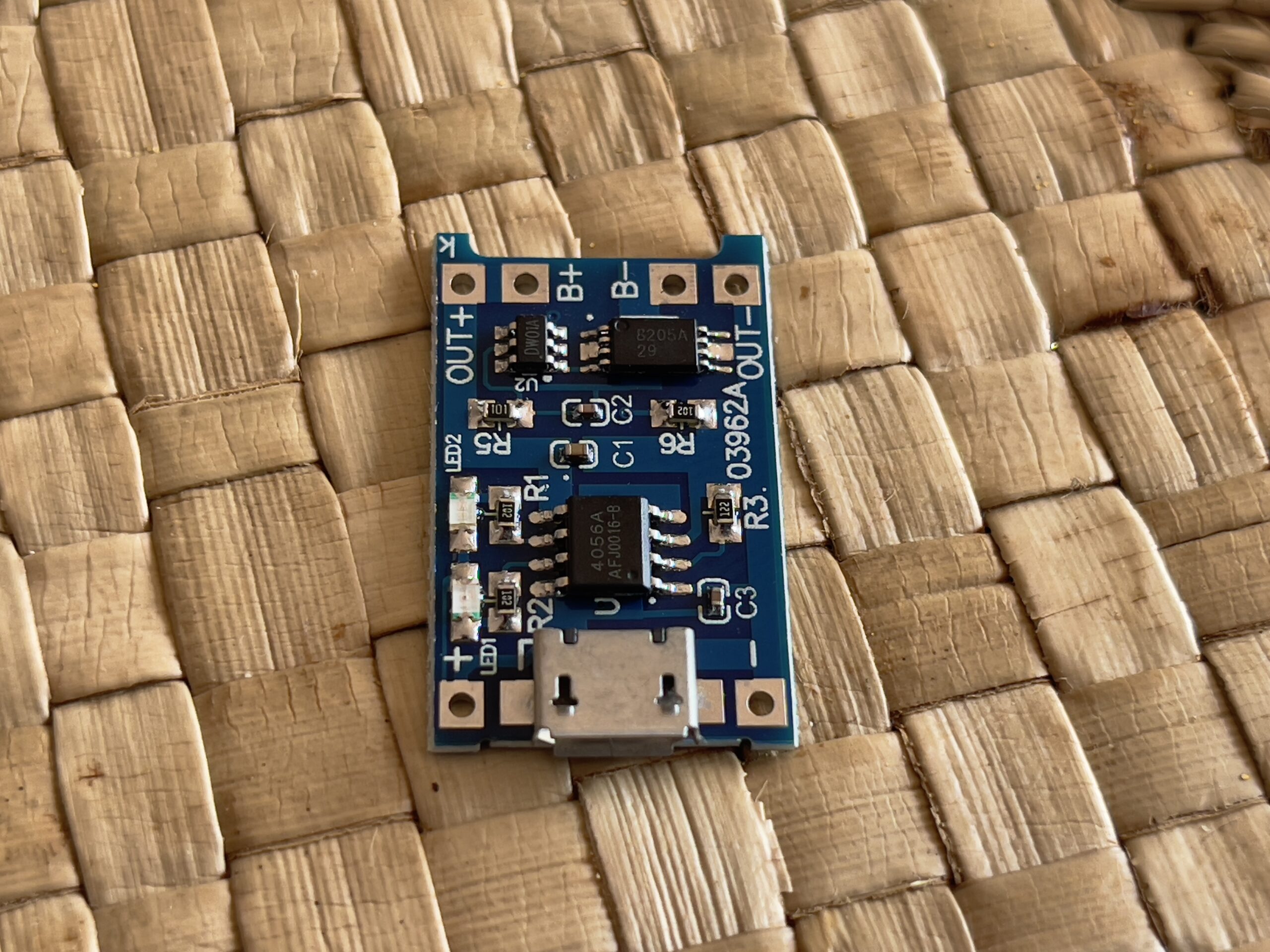
This is the TP4056 Lithium Ion Charging Board.
The one in the picture includes a MicroUSB socket, as well as LEDs to indicate the charge state of the connected Lithium Battery.
When your Development Board doesn’t include a Battery Circuit, this affordable and effective unit (or one of its many variants) is absolutely ideal to provide power from a Lithium Battery.
Connecting your Lithium Battery to the B+ and B- nodes (respectively), and wiring OUT+ to VIN on your Development Board, and OUT- to GND on your Development Board, is sufficient to drive any 3.3v Development Board from a Lithium Ion Battery.

However, many Development Boards (including the Arduino boards) require a 5v input voltage. So, how do we take a 3.3v supply and turn it into a stable 5v supply?
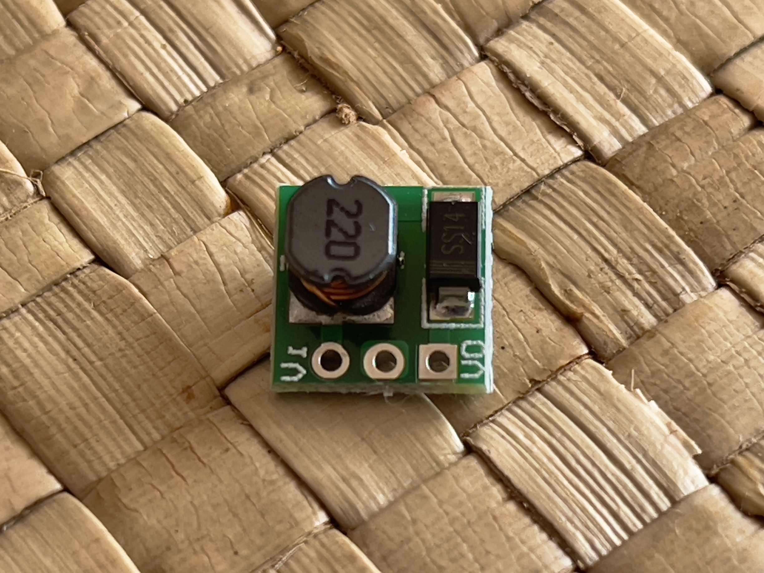
ME2108
5v
480mA
Step-Up Booster
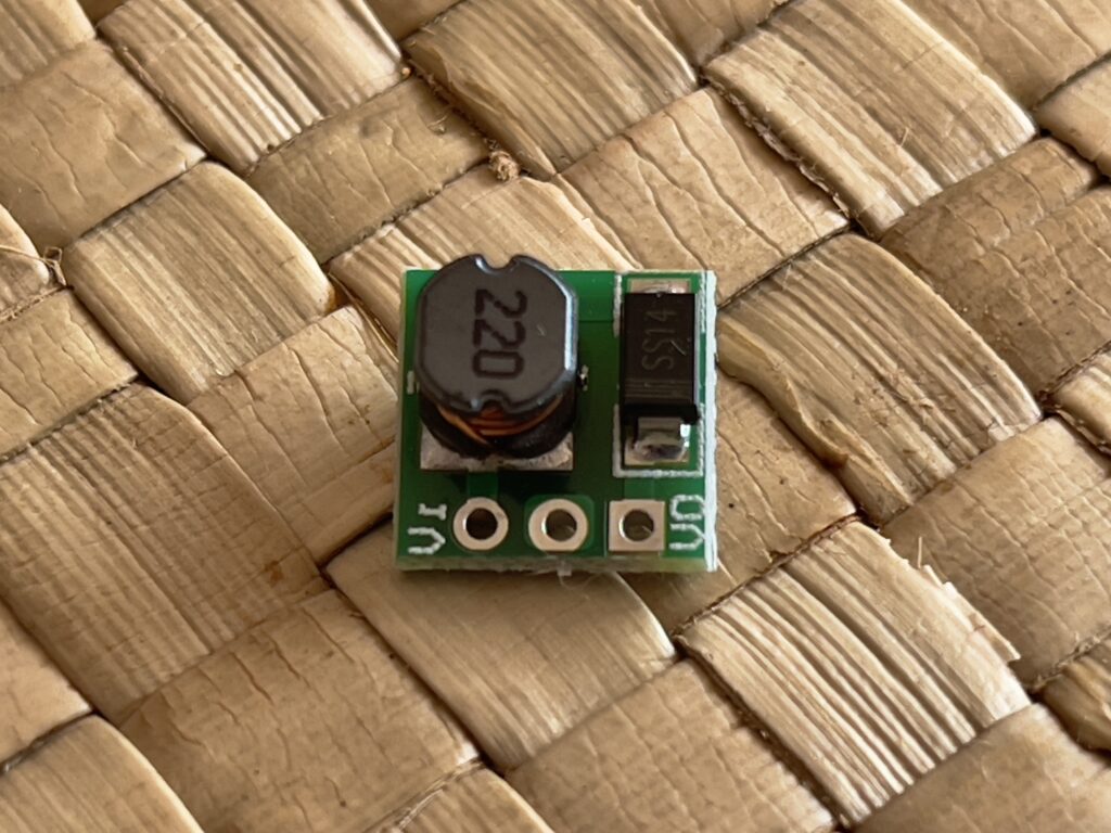
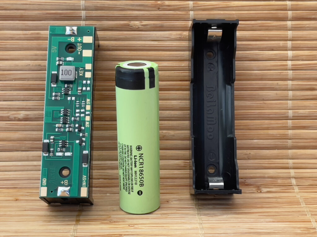
This is the ME2108 5v, 480mA, Step-Up Booster circuit.
Keep in mind that it has a maximum rated stable output of 480mA, which – while likely enough for most projects – might not be sufficient current for some higher-consumption projects.
Indeed, I would recommend a higher-output Step-Up Booster circuit for any project involving NeoPixels!
Anyway, this tiny little device takes an Input Voltage from your TP4056 Lithium Ion Charging board’s OUT+ into VI (Voltage In) on the ME2108, and the OUT- to the common Ground of the ME2108, and outputs 5v stable on VO (Voltage Out) of the ME2108.
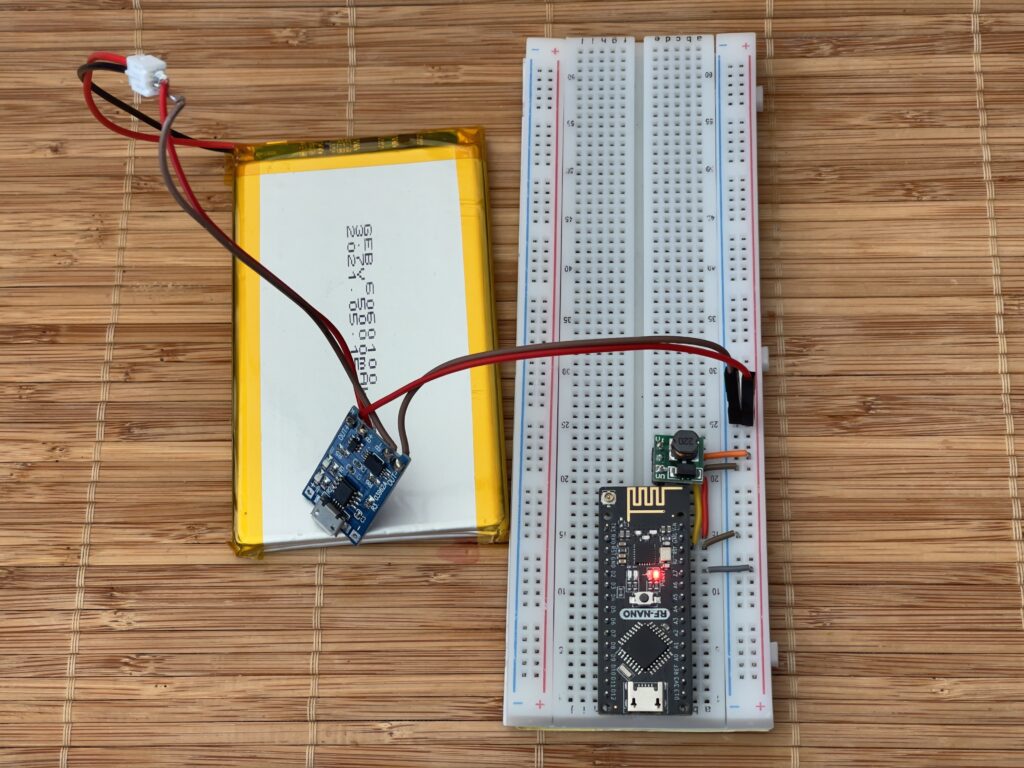
Connecting the Voltage Output (VO) of the ME2108 to the VIN of an Arduino, and of course connecting the common Ground to a GND pin of the Arduino, is absolutely sufficient to power the Arduino at 5v from a 3v Lithium Ion or Lithium Polymer Battery.
As you can see, the circuitry is fairly simple on a solderless prototype board. The best part is that we can charge the Li-Po battery while also powering the Development Board.
Now that we can provide power from, and we have the ability to safely charge, a Lithium battery; we need a means to measure the State of Charge for the Lithium battery within our software.
This is essential for presenting the remaining capacity percentage to the user(s) of your device(s), and to trigger any Power Management or Power Saving features your device might provide.
We can, for example, reduce the antenna power of radio modules when the Battery capacity drops below a threshold value, prolonging the runtime of the device at the possible expense of some performance that might not be required at that time.
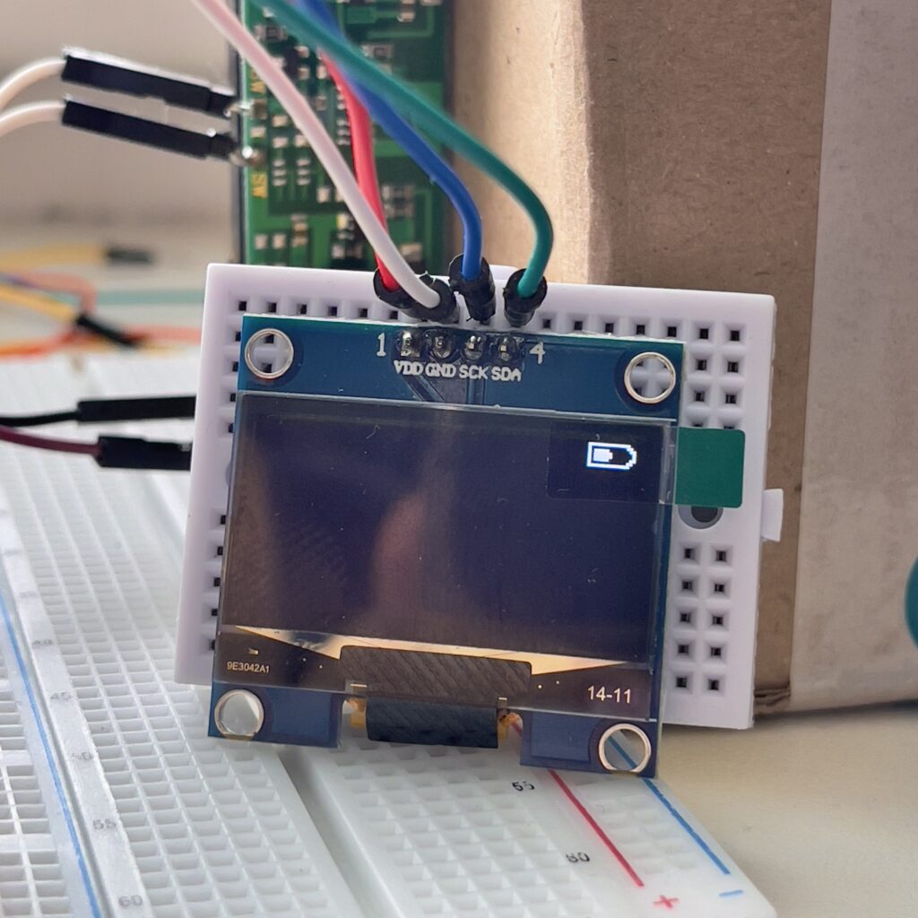
In the very least, we can notify the user(s) when the Battery requires recharging.

LTC4150
Coulomb Counter
Board
Coulomb Counters are devices that, in a nutshell, measure the flow of current in two directions. In our application, this would be the flow of current to (when charging) and from (when discharging) a Lithium Battery.
These elegant devices are the only reliable means of keeping track of the State of Charge of a Lithium Battery (both Lithium Ion and Lithium Polymer).
Not only can the LTC4150 notify our code every time the device is connected to and disconnected from an external power supply; it provides the means to measure the actual charging and discharging rates.
This in turn means we can accurately calculate the power consumption of different peripherals/accessories/inputs/outputs connected to our device.
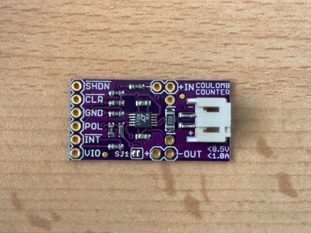
What you need to be aware of is that we need to physically configure the LTC4150 depending on the Input Voltage of our Device.
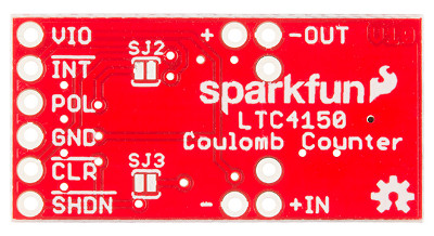
Leave Solder Headers SJ2 and SJ3 open for 5V devices.
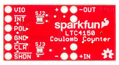
Close Solder Headers SJ2 and SJ3 for 3.3V devices.
This article uses the LTC4150 with both an Arduino Development Board, and an ESP32 Development Board, combined with the code we are going to produce and study.
The outcome: we will be able to represent the remaining capacity of a Lithium battery, determine whether it is charging or discharging from moment to moment, determine how much current is flowing in either direction, and – as an added bonus – calculate how much time remains before the battery is fully charged (if charging) or fully discharged (if discharging).
First, however, we need to discuss some considerations and limitations.
Limitation:
Capacity Rate Change
NOT
Initial Capacity!
The first fundamental limitation we need to know is that, while we are able to measure the flow of current in either direction (thus the rate of change) we cannot use a Coulomb Counter to determine the Initial Capacity of a Lithium battery.
Indeed, there is presently no way of calculating the exact remaining Capacity of a Lithium battery. There are many published scientific papers on Remaining Capacity Estimation for Lithium batteries, however, these still strike me as strictly theoretical documents.
Ultimately, you need to be aware that the LTC4150 isn’t going to give you a means to arbitrarily connect a Lithium battery and say “what is the initial capacity of this battery?”
You need to begin with a Lithium battery that is, ideally, fully charged. This way, we can reasonably specify that, the first time our code is ever executed, the Lithium battery capacity at that moment is equal to the Rated Capacity of the battery.
Put simply: if we – for the first time ever – flash our Arduino or ESP with code that contains the source we will be exploring shortly in this article, and we connect a battery rated at 2500mAh, we can safely initialise our Arduino or ESP with an initial Battery Capacity value of 2500mAh.
However, we can provide a little bit more flexibility by allowing for some degree of “Dynamic Recalibration” to compensate for any under- or over-estimates. We shall cover this in detail when we work through the source code in part two of this article.
Still, you do need to be aware that you can only measure change, not snapshot state using a Coulomb Counter such as the LTC4150.
Consideration:
For how long does my device need to function while on a battery?
One thing we need to consider is: how long does our device need to function while on a battery?
The answer can vary wildly from mere minutes, to hours, days, weeks, months, or – perhaps – even years.
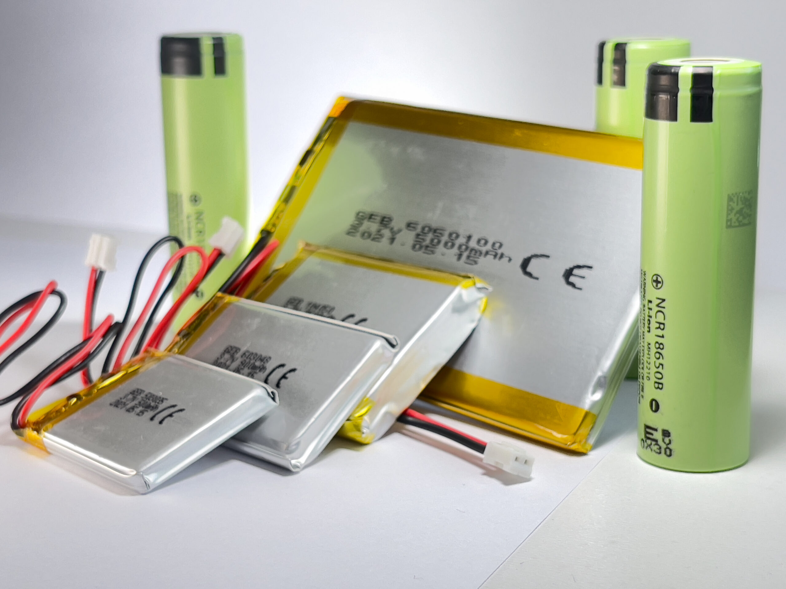
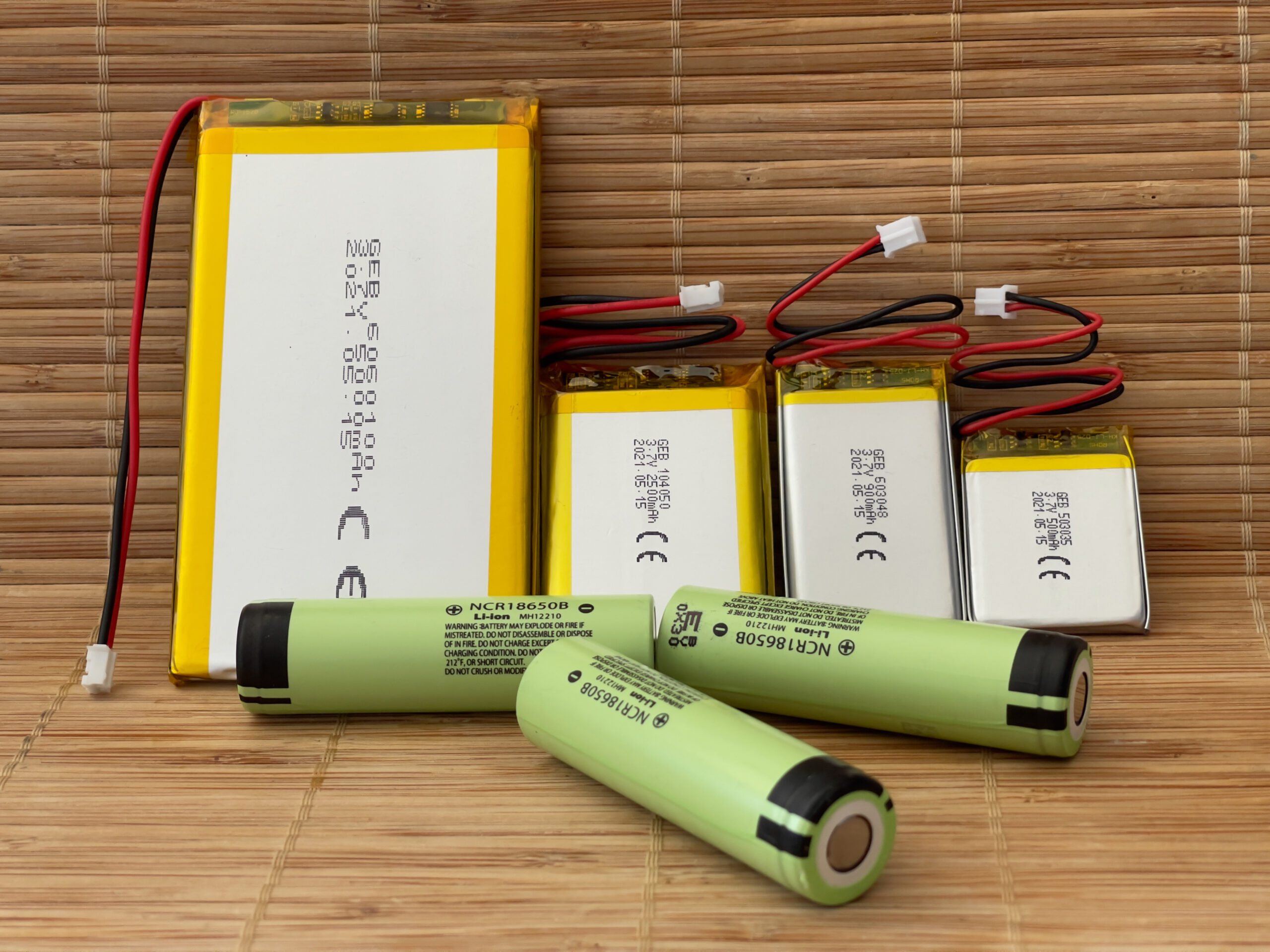
Still, answering this question is a fairly critical consideration. Yes, we could integrate a huge Lithium Polymer cell into our design (say, 5000mAh like the highest capacity cells shown in the photos accompanying this article) but doing so may be adding excessive cost (and make our device considerably larger/heavier) for absolutely no tangible gain.
Fortunately, calculating power requirements is usually fairly straight-forward.

Suggestion:
Calculate The Worst-Case Scenario
Back in 2016, I went to a Tesla car dealership (back when Tesla had dealerships) and asked one of the engineers working there (note: I’m paraphrasing the Engineer’s responses… this conversation happened many years ago):
Me: “Okay, so I can see the marketing blurb gives the Model X a range of 340 miles typical.”
Engineer: “Yes… and that’s an exceptional range compared with other EVs on the market!”
Me: “Yes, that sounds great, but I presume that’s based on some laboratory condition tests, right?”
Engineer: “Well, we try to combine ranges from different tests to calculate an average range…”
Me: “Okay, great… but here’s my question: what’s the WORST-CASE range?”
Engineer: “What do you mean?”
Me: “So, let’s presume the battery begins absolutely fully-charged, let’s presume we’re driving at the most battery-inefficient speed possible, then let’s turn on all the lights, the heating to maximum, stereo on full volume with the highest consumption input device, seat heaters… all the luxuries that can be turned on at the same time… continuously, all at the same time as fast-charging my phone with a 3A charger! Even the WIPERS turned on!”
Engineer: “Hmm… that’s a good question! Hang on, we can run some numbers for you now!”
The engineer left me to look at around the Model X for 5-10 minutes before returning.
Engineer: “74 miles!”
That is the actual worst-case mileage from full for the Tesla Model X back in 2016, as calculated by a group of three Telsa engineers working at the Westfield dealership in London in December 2016. If you’re reading this, Elon Musk, please feel free to run the numbers and let me know if you come up with something different.
Now, at the time, the engineer fielding my rather unusual query had a slightly pessimistic tone when he gave me the answer. However, I consider 74 miles as an absolute worst-case range for an electric vehicle (from fully-charged to dead) to be extremely impressive!
What impressed me more was that there were two more engineers stood by the door behind him, and he had their calculations written on paper in his hand!
When calculating battery capacity requirements, I tend to calculate always against the worst possible case scenario (switching everything on that can possibly be consuming power simultaneously, and calculate based on a constant consumption rate of whatever current to which that equates).
This is the number that most interests me. I don’t care how long a battery could last under some laboratory idealistic conditions! I want to know how long it would last in the worst possible situation.
Now, Tesla rate and calculate their batteries in Kilowatt Hours (kWh). In microelectronics, we tend to calculate current and battery capacities in Milliamp Hours (mAh).
To bring this article back on-topic, we can actually use our LTC4150 to calculate this worst-case scenario for us!
The mathematics is fairly simple:
Calculate Runtime (Hrs) using Battery Capacity (mAh) and Consumption Rate (mAh)
Combined Maximum Consumption rate in mAh (we shall call this C)
Rated Capacity of Battery in mAh (we shall call this T)
We define “Runtime” as being the amount of time – in hours – a full Battery can last while discharging at a constant rate of C (we shall call this R).
R = T / C
Pretty simple, right?
We know the rated capacity of our battery [T] (it’s printed on the casing of the cell). We can use the LTC4150 to calculate discharge rate [C] as you will see in the source shortly in this article. Simply by dividing the Consumption [C] from the Capacity [T], we get the number of Runtime Hours [R] (a decimal value).
So, let’s plug in a hypothetical.
Our Battery is rated at 2500mAh [T = 2500]
Our Hardware’s maximum peak Consumption Rate is 250mAh [C = 250]
R = 2500 / 250 = 10
Therefore, a 2500mAh battery could power a device consuming 250mAh for a maximum possible total of 10 hours.
It should be noted that most cells won’t actually provide their full rated capacity to be consumed. Lithium batteries cannot be allowed to fully discharge, and most contain an integrated circuit to shut off the flow of current when it drops below a threshold.
However, since we are calculating an absolute worst-case scenario, presuming that the peak consumption rate is constant – when in reality it would never be so high – 10 hours is a safe worst-case estimate.
We an also do the inverse:
Calculate required Battery Capacity (mAh) to facilitate Consumption Rate (mAh) for a given Runtime (Hrs)
Since we know the peak combined Consumption [C], we can calculate the required Battery Capacity [T] using a desired Runtime [R].
T = C * R
So, let’s go back to our hypothetical and say that we have a peak Consumption Rate of 250mAh [C = 250].
Let’s say that we only require that our Device be capable of running for 5 continuous hours on a Battery [R = 5]
T = 250 * 5 = 1250mAh.
And, just like that, we know that we can use a 1250mAh rated battery to safely provide power for at least 5 hours of continuous operation. In most cases, this would likely leave a significant margin for longer runtimes (possibly even as high as 8-9 hours, depending on the typical consumption rate of your device) but guarantees you meet your minimum requirements without too much excess.
If you have an ammeter, you can calculate the peak consumption rate of your device easily. If you don’t, we will later demonstrate how to use the LTC4150 to do the same. Essentially, you can think of the LTC4150 as being a slightly more sophisticated ammeter.

Wiring
The
LTC4150
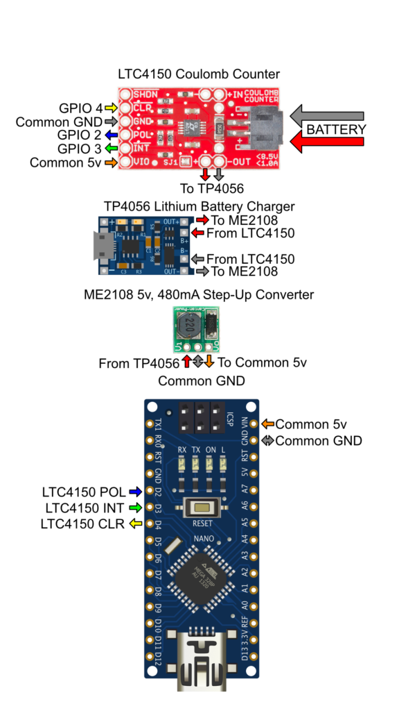
Arduino
Most Arduino boards have a limitation of only providing two Digital GPIO pins that may be used as an Interrupt (ISR) pin.
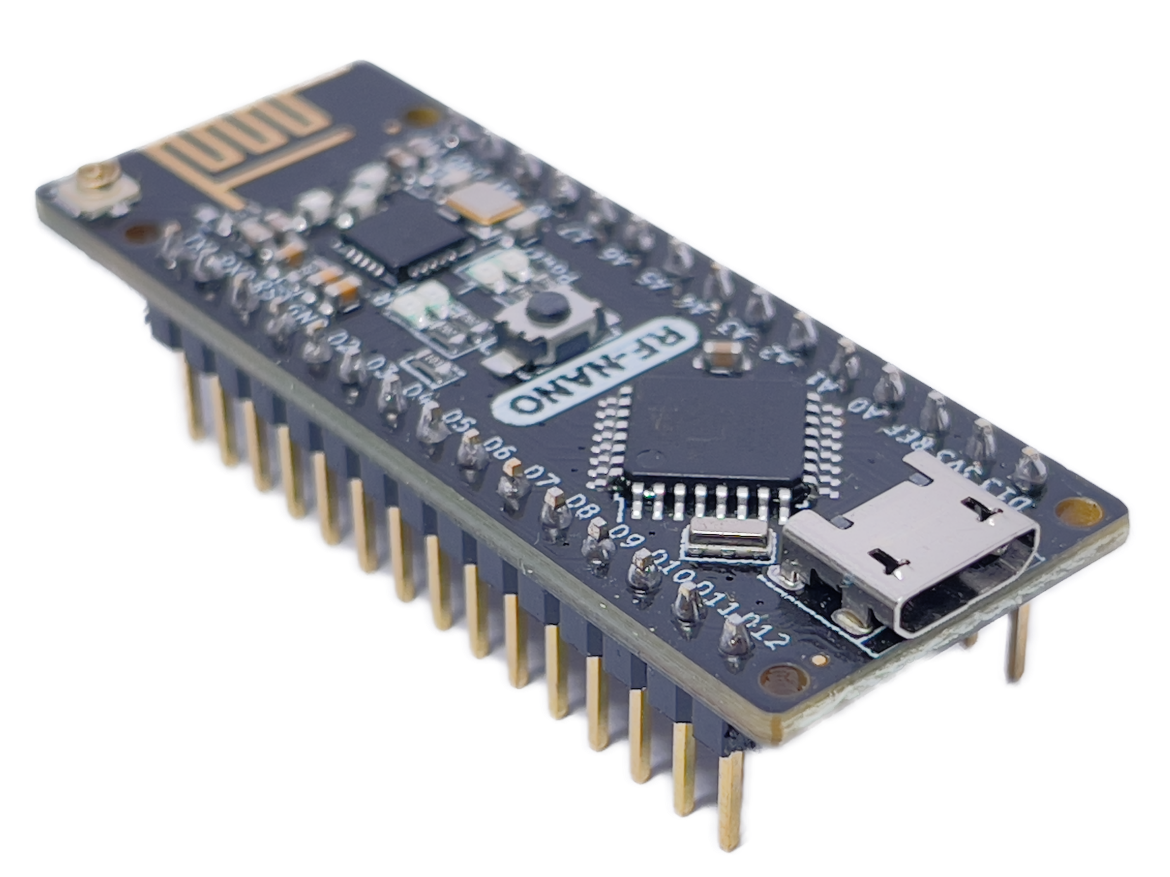
For example, the ATMega328-based Arduino boards (such as the Uno, the Nano, and even the RF Nano pictured above) only allow pins D2 and D3 to be configured as Interrupts.
If you can possibly make both of those pins available for the LTC4150 (if you don’t require Interrupts for any sensors connected to your device) then I recommend using the first wiring diagram (the one for Interrupt Mode).
If you cannot spare these pins, or you do not wish to use Interrupts (ISRs) for some other reason, use the second wiring diagram (Non-Interrupt Mode).
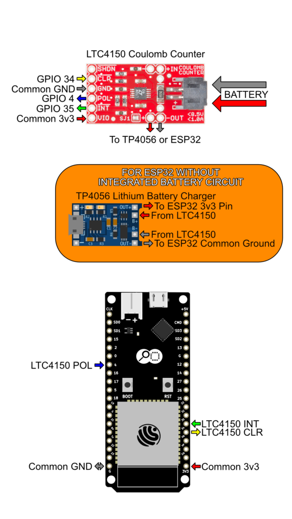
ESP32
Wiring for the ESP32 is considerably more permissive than wiring for the Arduino.
Unlike most Arduino boards, every available GPIO pin on the ESP32 may be used as an Interrupt (ISR) pin. For this reason, I highly recommend you use the first wiring diagram (the one for Interrupt Mode)
If there is a reason why you cannot or do not wish to use Interrupts (ISRs), you can use the second wiring diagram (Non-Interrupt Mode).
Method 1 – Interrupt Mode Wiring
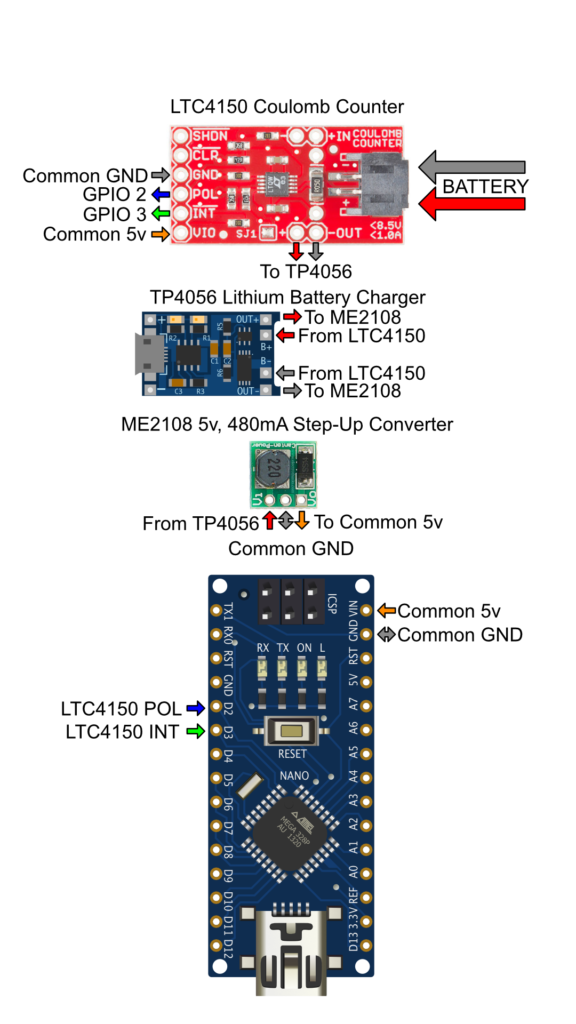
| Arduino (ATMega328) | LTC4150 | Direction |
|---|---|---|
| GPIO 2 (Interrupt Pin) | POL | INPUT |
| GPIO 3 (Interrupt Pin) | INT | INPUT |
| GND | GND | – |
| 5V | VIO | – |
Method 1 – Interrupt Mode Wiring

| ESP32 | LTC4150 | Direction |
|---|---|---|
| GPIO 4 | POL | INPUT |
| GPIO 35 | INT | INPUT |
| GND | GND | – |
| 3V3 | VIO | – |
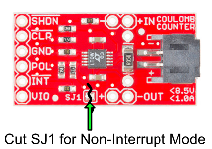
Method 2 – Non-Interrupt Wiring
Before you can use the LTC4150 without Interrupts, you will need to unsolder header SJ1 as shown in the following image:
| Arduino (ATMega328) | LTC4150 | Direction |
|---|---|---|
| GPIO 2 | POL | INPUT |
| GPIO 3 | INT | INPUT |
| GPIO 4 | CLR | OUTPUT |
| GND | GND | – |
| 5V | VIO | – |
Method 2 – Non-Interrupt Wiring
Before you can use the LTC4150 without Interrupts, you will need to unsolder header SJ1 as shown in the following image:
| ESP32 | LTC4150 | Direction |
|---|---|---|
| GPIO 4 | POL | INPUT |
| GPIO 35 | INT | INPUT |
| GPIO 34 | CLR | OUTPUT |
| GND | GND | – |
| 3V3 | VIO | – |
Please note that, for Non-Interrupt Mode, you can substitute the GPIO pins defined in the wiring diagrams as necessary.
For the ESP32, you can also choose different pins when using Interrupt Mode (all available pins support Interrupts on the ESP32)
If you choose different pins, remember to keep track of them, as you will have to make the corresponding pin number changes in the upcoming source code (in part two of this article).
You may have noticed that Non-Interrupt Mode requires an additional wire. This is because, when in Interrupt Mode, the LTC4150 will automatically reset the state of the INT (Interrupt) pin immediately. However, when in Non-Interrupt Mode, our code needs to manually reset the state by toggling the CLR (Clear) Pin of the LTC4150.
For this reason, it is simpler to use the LTC4150 in Interrupt Mode where possible.
Understandably, using Interrupts isn’t necessarily suitable for all applications, which is why we are taking the time to understand both Interrupt and Non-Interrupt Modes equally.

Coming Up in Part Two:
A Library for Battery-Powered
Arduino and ESP32 Devices
We now have our Arduino or ESP32 wired up with a Coulomb Counter, have the means to calculate the required Battery Capacity to run our device for a desired amount of time, and have a better understanding of the what, the why, and the how.
In Part 2, we’re going to proceed away from the physical world of wires and PCBs, and instead begin to produce a piece of code to monitor the State of Charge for our Lithium Battery.

Very much enjoying the article, but am missing the second part.
It appears 2 of 2 is not published.