

Review-Tutorials?
Before we begin, we want to briefly explain the format of this Review article.
Where most publications produce Reviews as strictly-informational articles covering a particular product or service; Flowduino is all about education!
For this reason, we present every Review with at least one Tutorial element.
After all, how better to review a Microcontroller, Sensor, IO device, or Development Board than to walk through a project using them?
So, please enjoy this Review-Tutorial (“Reviewtorial?”)
The Problem…
We here at Flowduino build a lot of wirelessly interconnected devices. No, seriously! More than half of all of the projects we develop require multiple devices to communicate without wires, sometimes over vast distances.
We have, at times, gone so far as to build line-of-sight optical laser communications into our devices, sometimes even with optical repeater devices necessary to span distances of multiple kilometres, where low-latency is a concern.
Readers with more experience working with Arduino and other MCUs will very likely have experienced adding radio modules to their devices. There is certainly no shortage of choice in this area, either!
From the most simple modules, such as the 433MHz HC-12 UART radio, to the slightly more complex nRF24L01 SPI, or Bluetooth (JDY-33, DW-CT14, AT-09 etc), or WiFi, or LoRa, or even GPRS/LTE… the options are practically limitless.

These days, Arduino manufacture their IoT range of development boards, which feature WiFi and/or Bluetooth on-chip. However, these come at a higher price point, and – as with all things – have their own disadvantages.
So, what if you need radio communication between multiple devices, but want to use a simple, low-profile development board without having to attach a separate radio to it? What if Bluetooth and WiFi aren’t suitable?
The RF-Nano (a Solution)
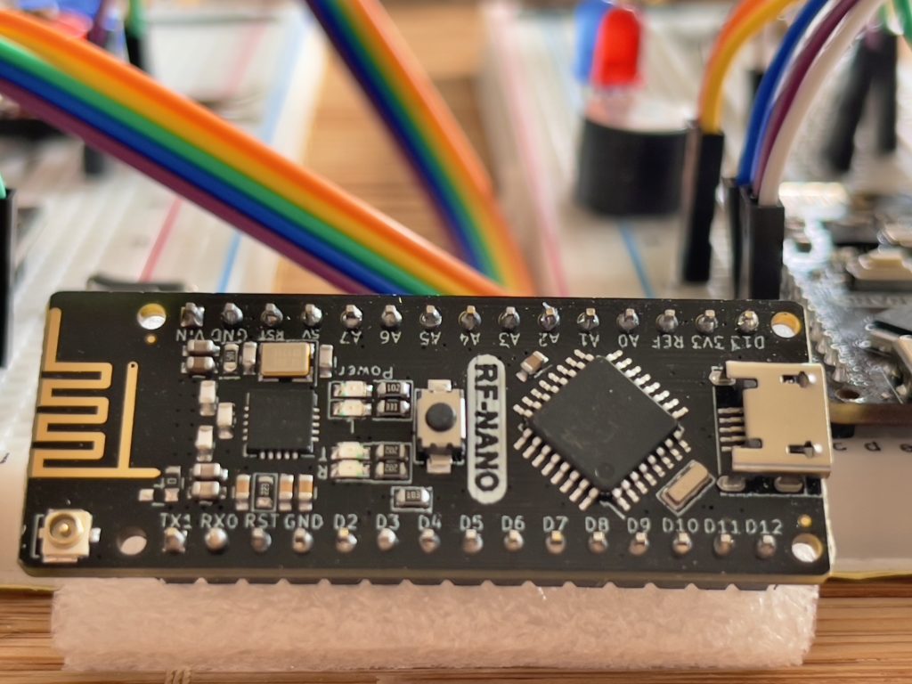
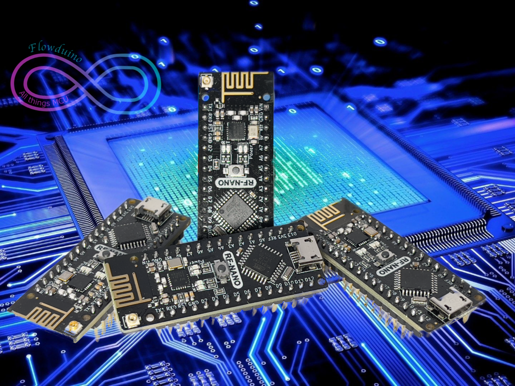
Introducing the RF-Nano V3.0, from eMakefun!
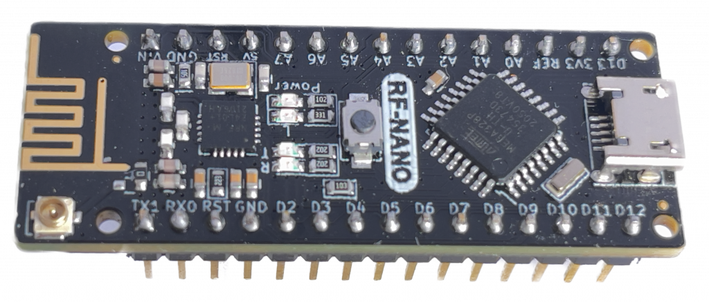
The RF-Nano combines the simplicity and compatibility of the Arduino Nano R3’s ATmega328 with the usefulness of the nRF24L01+ 2.4GHz radio transceiver.
No more multi-wire SPI connection required!


Working our way down the board from the top of this photograph:
- A Micro-USB socket… an improvement over the official Arduino Nano R3’s Mini-USB socket.
- Beneath that in the middle we have the ATmega328 chip
- You can then see the Reset button
- Followed by some SMD components and the LEDs for power, TX, RX etc.
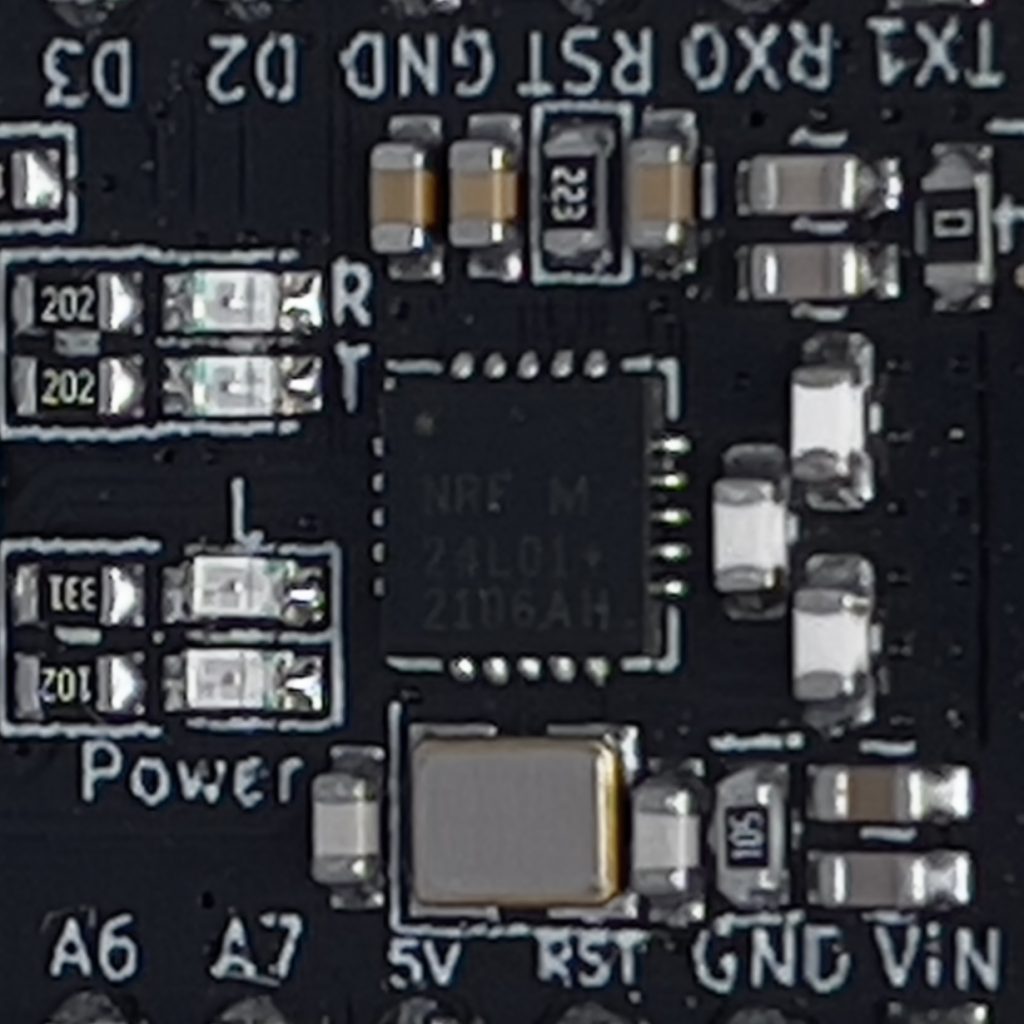
- Beneath that is the nRF24L01+ chip. This is what gives the RF-Nano the integrated 2.4GHz radio functionality.
- At the bottom, in the centre, we see a PCB Antenna for the nRF24L01+
- Bottom-right, we have a socket for connecting an SMA or RP-SMA antenna pigtail. This allows us to use an External Antenna, increasing (considerably) the communication range.
Down the left- and right-hand sides, we have the GPIO pins, which are verbatim identical to those from the Arduino Nano R3.
Packaging
The RF-Nano comes in a very small cardboard box.
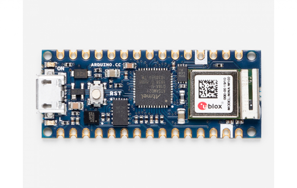
The printing on the box is nice, albeit bearing an illustration of the Arduino Nano R3 rather than the RF-Nano.
Inside, it contains the RF-Nano board itself, embedded into a piece of foam to offer some protection from physical impacts.

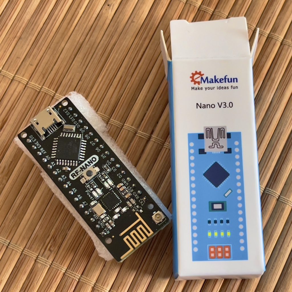
Just be aware that there is no form of static-proof packaging, or even plastic coverings on either the board or the box.
This means that damage could occur in storage or transit, depending on the conditions under which your chosen supplier looks after its stock.
Fortunately for me, my preferred supplier takes impeccable care of their stock, ensures that all outbound packages are suitably packed and protected, and I have had no problems with the 7 RF-Nano boards I have ordered for testing.
Specifications
| Feature | Value |
| Microcontroller | ATmega328P |
| Clock | 16MHz |
| Flash | 32KB |
| GASH | 2KB |
| EEPROM | 1KB |
| USB-Serial Bridge | CH340G |
| Digital I/O Pins | 14 |
| PWM Pins | 6 |
| Analog Input Pins | 8 |
| DC Current-per-Pin | 40mA |
| Input Voltage | 6-20V recommended (5V works fine) |
| 5V Max Current | 800mA |
| 3.3V Max Current | 180mA |
| Weight | 15g |
| Addressable Registers | 3 (PORTB, PORTC, PORTD) |
| Radios-on-board | Yes: nRF24L01+ |
| Antennas | Yes: 1x PCB + 1x U.FL 1.15mm Pigtail Socket |
| Persistent Storage | No |
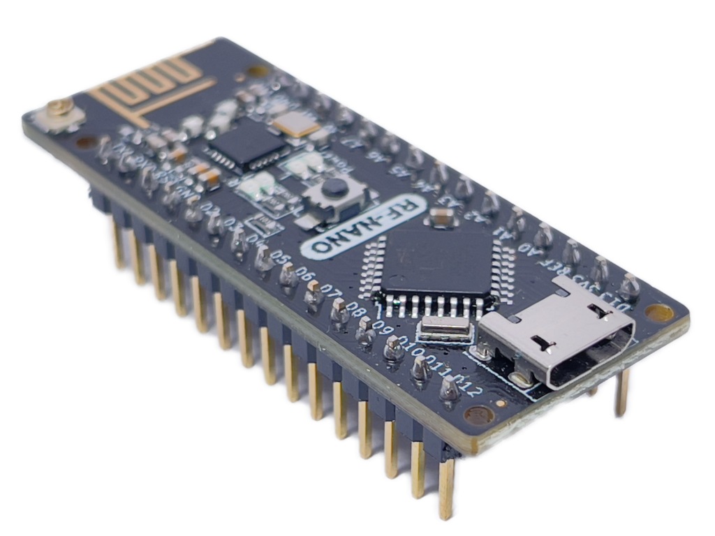
| Solder Pins | Yes, Pre-soldered |
| Packaging | Foam insert in Cardboard. No Static-Proof Bag! |
| USB Interface | Micro-USB Socket (Female) |
| Buttons on-board | Yes: Reset |
| LEDs on-board | Yes: Power, Flash, RX, TX |


As you can see, the Microcontroller specifications are identical to the Arduino Nano R3 development board. This means you can do a direct MCU swap on existing projects or prototypes using the Arduino Nano R3 dev board, for Nano-RF dev boards.
Unavailable Pins!
It must be noted that the nRF24L01+ chip is connected to the ATmega328P chip directly on the board. This means that there are SPI pins on the GPIO that you can no longer use for other purposes.
I shall list these pins, and what they’re connected to, now:
| GPIO Pin Number | nRF24L01+ SPI |
| D9 | CE (Chip Enable) |
| D10 | CS/CSN (Chip Select) |
| D11 | MOSI |
| D12 | MISO |
| D13 | SCK |
Important Note: The RF-Nano official documentation has CE and CS listed in the wrong order! Our table here has the correct Pin assignments. This matters because, if you reverse CE and CS, the radio will initialise just fine, but you won’t be able to transmit or receive anything with it. We wasted an awful lot of time trying to figure this one out! Hopefully, we just saved yours.
So, just be aware that you cannot use these listed SPI pins on the GPIO pin header for anything else. This isn’t a problem, mind you, as you would have to use these same pins on an Arduino Nano R3 if you wanted to connect an external SPI radio module.
Let’s build something with two RF-Nanos!
Okay, so we’ve taken a look at the specifications, and acknowledged the handy advantages that a board integrating a 2.4GHz radio can have for our projects.
Now, let’s actually test these boards and see how quickly and easily we can make two devices talk to each other!
We’re going to make a simple RGB light unit, with a Radio Remote Controller!
Ingredients…
This recipe requires two breadboards, and two RF-Nano development boards.
Per-board, you will need:
- 1x RGB LED (or a separate Red, Green, and Blue LED – respectively)
- 3x 330 Ohm Resistors
One of the two boards will also require:
- 3x Momentary-Push Buttons
- 3x 1 kOhm (1000 Ohm) Resistors
Wiring…
There are two similar wiring diagrams for this project.
The RGB Display (Receiver) Board

![RF-Nano Demo - Receiver [Fritzing]](https://flowduino.com/wp-content/uploads/2021/08/RF-Nano-Demo-Receiver_bb-1024x367.png)
I’ve chosen to illustrate this wiring diagram using separate LEDs for Red, Green, and Blue (respectively) simply because it is easier to visualise. You can, of course, just as easily connect the resistors to the R, G, and B legs of a single RGB LED.
I ask that you forgive that the dev board shown in the illustration is the Arduino Nano R3 rather than the RF-Nano… I was unable to find the RF-Nano part available for Fritzing.
GPIO Pin wiring:
| GPIO Pin | Direction | Connects to… |
| D2 | Output | Red LED via 330Ohm resistor |
| D3 | Output | Green LED via 330Ohm resistor |
| D4 | Output | Blue LED via 330Ohm resistor |
The Remote (Transmitter/Controller) Board
The Remote (Transmitter/Controller) Board is wired identically with LEDs and resistors, to the same pins of the RF-Nano.
However, we add 3 components to this board: push buttons.

![RF-Nano Demo - Transmitter [Fritzing]](https://flowduino.com/wp-content/uploads/2021/08/RF-Nano-Demo-Transmitter_bb-1-1024x437.png)
So, for the Remote (Transmitter/Controller) Board, the GPIO Pin Wiring looks like this:
| GPIO Pin | Direction | Connects to… |
| D2 | Output | Red LED via 330Ohm resistor |
| D3 | Output | Green LED via 330Ohm resistor |
| D4 | Output | Blue LED via 330Ohm resistor |
| D5 | Input | Button to control Red LED |
| D6 | Input | Button to control Green LED |
| D7 | Input | Button to control Red LED |
The Code
Let’s quickly put together the code for this project, but – before we do – we are going to begin with an obligatory reminder about coding standards and principles.
Examples are NOT the way you should write your code!
Please note that, for the sake of keeping this article concise, these code examples will follow the common “Arduino IDE” approach of putting all of our code into a single source file (a Sketch in the context of the Arduino IDE).
I want to preface this by stating that I do not condone developing code in this manner for real-world projects. Real-world code should always be written with the SOLID principles of development at its core.
On to the code!
For this project, we will be using the RF24 library. This Library is available in both the Arduino IDE, as well as PlatformIO.
We develop and maintain our projects using PlatformIO.
RGB Remote (Transmitter) Code
#include <Arduino.h>
#include <SPI.h>
#include <RF24.h>
#define PIN_LED_RED 2 // D2
#define PIN_LED_GREEN 3 // D3
#define PIN_LED_BLUE 4 // D4
#define PIN_BTN_RED 5 // D5
#define PIN_BTN_GREEN 6 // D6
#define PIN_BTN_BLUE 7 // D7
#define PIN_RF_CE 9 // D9 = Chip Enable (CE) for nRF24L01+
#define PIN_RF_CS 10 // D10 = Chip Select (CS) for nRF24L01+
#define CHANNEL_READ 987654321
#define CHANNEL_WRITE 123456789
/*
RGBState
We will Transmit and Receive this State data.
*/
struct RGBState {
bool Red; // True if the Red button is Down
bool Green; // True if the Green button is Down
bool Blue; // True if the Blue button is Down
};
RGBState currentState;
RF24 radio(PIN_RF_CE, PIN_RF_CS);
bool radioReady = false;
void setup() {
// Initialise Serial first
Serial.begin(115200);
// Pin modes
pinMode(PIN_LED_RED, OUTPUT);
pinMode(PIN_LED_GREEN, OUTPUT);
pinMode(PIN_LED_BLUE, OUTPUT);
pinMode(PIN_BTN_RED, INPUT);
pinMode(PIN_BTN_GREEN, INPUT);
pinMode(PIN_BTN_BLUE, INPUT);
// Configure the Radio
int failCount = 0;
while (!radioReady && failCount < 10) {
radioReady = radio.begin();
if (!radioReady) {
failCount++;
Serial.print("Radio Initialisation Failed ");
Serial.print(failCount);
Serial.println(" times.");
}
}
if (!radioReady) {
Serial.println("Radio could not be initialised!");
return;
}
radio.setDataRate(RF24_2MBPS); // Maximum Bandwidth
radio.setPALevel(RF24_PA_MAX); // Maximum Range
radio.setPayloadSize(sizeof(RGBState)); // Size of the Data we will Transmit
radio.setAutoAck(true); // Allows us to check if the Transmission Succeeded
// We technically don't need to open a Reading Pipe for a Transmit-Only Device!
radio.openReadingPipe(1, CHANNEL_READ); // For Incoming Data
// We need to open the Writing Pipe in order to Transmit data
radio.openWritingPipe(CHANNEL_WRITE); // For Outgoing Data
}
inline void sendState() {
if (!radio.write(¤tState, sizeof(RGBState))) {
Serial.println("Transmission failed!"); // We output errors to Serial.
}
}
void loop() {
if (!radioReady) {
digitalWrite(PIN_LED_RED, HIGH); // Turn the Red LED on to show failure
return; // We cannot continue if the Radio isn't working!
}
// We need a LOCAL State so we can Compare later!
RGBState newState;
// Let's populate the LOCAL State
newState.Red = digitalRead(PIN_BTN_RED);
newState.Green = digitalRead(PIN_BTN_GREEN);
newState.Blue = digitalRead(PIN_BTN_BLUE);
// Now we see if anything changed
if (
newState.Red != currentState.Red ||
newState.Green != currentState.Green ||
newState.Blue != currentState.Blue
) {
// Update the Current State
currentState = newState;
// Show the State on the Controller's LEDs
digitalWrite(PIN_LED_RED, currentState.Red);
digitalWrite(PIN_LED_GREEN, currentState.Green);
digitalWrite(PIN_LED_BLUE, currentState.Blue);
sendState(); // Send the State to all Receivers
}
}
The example code (above) is fully-annotated, so I won’t conflate this article by repeating what has already been said. Simply read through the above code… it is pretty simple to understand.
RGB Display (Receiver) Code
#include <Arduino.h>

#include <SPI.h>
#include <RF24.h>

#define PIN_LED_RED     2   // D2
#define PIN_LED_GREEN   3   // D3
#define PIN_LED_BLUE    4   // D4

#define PIN_RF_CE       9   // D9 = Chip Enable (CE) for nRF24L01+
#define PIN_RF_CS       10  // D10 = Chip Select (CS) for nRF24L01+

#define CHANNEL_READ    123456789 // Opposite of the Remote code
#define CHANNEL_WRITE   987654321 // Opposite of the Remote code

/*
  RGBState
  We will Transmit and Receive this State data.
*/
struct RGBState {
  bool Red;   // True if the Red button is Down
  bool Green; // True if the Green button is Down
  bool Blue;  // True if the Blue button is Down
};

RGBState currentState;
RF24 radio(PIN_RF_CE, PIN_RF_CS);
bool radioReady = false;

void setup() {
  // Initialise Serial first
  Serial.begin(115200);

  // Pin modes
  pinMode(PIN_LED_RED, OUTPUT);
  pinMode(PIN_LED_GREEN, OUTPUT);
  pinMode(PIN_LED_BLUE, OUTPUT);

  // Configure the Radio
  int failCount = 0;

  while (!radioReady && failCount < 10) {
    radioReady = radio.begin();
    if (!radioReady) {
      failCount++;
      Serial.print("Radio Initialisation Failed ");
      Serial.print(failCount);
      Serial.println(" times.");
    }
  }

  if (!radioReady) {
    Serial.println("Radio could not be initialised!");
    return;
  }

  radio.setDataRate(RF24_2MBPS); // Maximum Bandwidth
  radio.setPALevel(RF24_PA_MAX); // Maximum Range

  radio.setPayloadSize(sizeof(RGBState)); // Size of the Data we will Transmit
  radio.setAutoAck(true); // Allows us to check if the Transmission Succeeded

  // We need to open the Reading Pipe in order to Receive data
  radio.openReadingPipe(1, CHANNEL_READ); // For Incoming Data
  // We don't need to open the Writing Pipe on a Receive-only Device
  radio.openWritingPipe(CHANNEL_WRITE); // For Outgoing Data

  radio.startListening(); // This starts the radio listening for incoming messages
}

void loop() {
  if (!radioReady) {
    digitalWrite(PIN_LED_RED, HIGH); // Turn the Red LED on to show failure
    return; // We cannot continue if the Radio isn't working!
  }

  if (!radio.available()) { return; } // No need to continue

  RGBState inboundState;
  radio.read(&inboundState, sizeof(RGBState));

  digitalWrite(PIN_LED_RED, inboundState.Red);
  digitalWrite(PIN_LED_GREEN, inboundState.Green);
  digitalWrite(PIN_LED_BLUE, inboundState.Blue);
}
Again, the above code is heavily-annotated to describe in sequence what is happening. You simply need to read through it carefully.
What I will point out is that the main differences are at the end of the setup() and loop() methods, which deal with the specifics of receiving rather than transmitting.
Grab the Sample Code on GitHub
Flowduino has a GitHub account specifically to provide complete sample projects accompanying the articles on this website.
The complete Sample Projects for this article can be found here.
Running the Demo
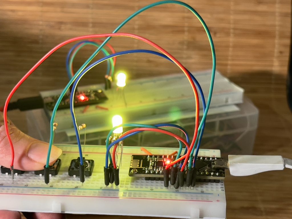
So, we now have a Remote (Transmitter) and an RGB Display (Receiver). Whenever you press one of the buttons representing a colour (Red, Green, and Blue – respectively) the lights will simultaneously illuminate on both devices.
If you press multiple buttons, you will combine colours… which is pretty fun.
What’s important to note is that we are transmitting multiple values in a structured object. We can transmit basically any kind of data we want this way.
The Price
The RF-Nano is what I would call “competitively-priced”. While there are certainly cheaper Arduino Nano R3 clones on the market, these don’t feature the integrated radio. Once the cost of the radio module is factored in, the RF-Nano ultimately comes in at approximately the same overall price.
When you consider the reduced complexity, potential time-savings when it comes to fault-finding and troubleshooting, the price becomes a bargain.
In Conclusion…
The RF-Nano is an extremely useful development board, which eliminates the potential fault-finding effort we have to endure when a device-to-device project starts experiencing communication problems.
Since the radio is integrated directly into the development board, we can rule out radio hardware issues entirely, and focus on the software possibilities.
The overall quality is impressively high, and easy to use.
If you’re using an Arduino with the ATmega328 microcontroller, and you want to add a low-latency, high-frequency radio… swap out your dev board for the RF-Nano. It’s pin-compatible; albeit you can’t attach anything to the SPI pins, as explained previously – but an external radio would have to occupy these pins anyway.
The Photographs in this Article…
We just want to take a moment to point out that every single photograph of the RF-Nano used in this article has been taken by the Simon, of Flowduino, whom also authored this article.
The images were all taken, and – where applicable – edited, on a mobile phone.
We hope you like them… and if you do decide to use them on your own publications (online or physical) we would very-much appreciate it if you would provide accreditation. Something like “Photo by Flowduino.com” would be perfect. Permission for use elsewhere is explicitly granted under that sole condition.